
Diagnostic Worksheets
It’s always best to check out the charge-start system to diagnose your problem before removing the starter or alternator from the engine. We offer assistance in trouble-shooting the starter, the alternator, and the overall charge-start system. Available as either down-loadable Diagnostic Worksheets or as You-Tube videos (see the reference section of this website), our installation guides will walk you through the process of removing your old part and installing the new part.
SAFETY PRE-CAUTIONS:
-
ALWAYS PERFORM DIAGNOSTIC WITH TRANSMISSION SET IN NEUTRAL OR PARK, PARKING BRAKE SET, AND ALL ELECTRICAL LOADS OFF.
-
WEAR FACE AND EYE PROTECTION AT ALL TIMES WHILE PERFORMING DIAGNOSTIC.
Following this worksheet will help determine if there is an issue with a starter motor or an alternator and help prevent warranty denials for No Trouble Found (NTF).
STEP 1 – TEST INDIVIDUAL BATTERIES
- Remove the battery’s surface charge.
- Test the battery’s state-of-charge. Each battery must have at least a 75% state-of-charge (12.45 V for flooded or 12.60 V for AGM).
- Load test each battery in the pack.
- Charge/replace bad batteries before proceeding to step
STEP 2 – TEST BATTERY CABLES
- Test interconnection between batteries by measuring the Voltage of each battery with a 500 Amp load applied. The difference should be less than 0.1 Volts (0.2 mΩ).
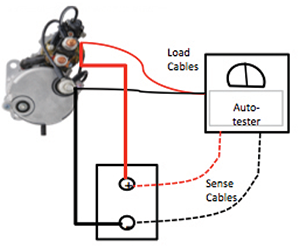
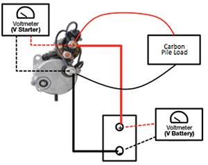
- Test the cables from the battery box to the starter by measuring the voltage drop. The Voltage difference should be less than 0.5 Volts with a 500 Amp load applied (1 mΩ). The load clamps must be connected to the starter side.
Battery Cable Test Diagrams
Battery Cable Test with Automated Tester
Battery Cable Test with Carbon Pile
STEP 3 – TEST CONTROL CIRCUIT
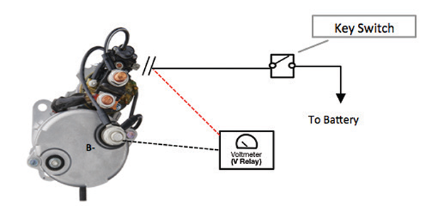
- Disconnect the signal wire from the starter.
- Turn Key Switch to crank position.
- Check Relay voltage. Voltage must be at least 11.4 V.
Control Circuit
STEP 4 – TEST ALTERNATOR CABLES
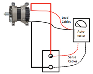
- Test the cables from the battery box to the alternator by measuring the voltage drop. The Voltage difference should be less than 0.5 Volts with the alternator output rating used as the load. The load clamps must be connected to the alternator side.
Battery Cable Test Diagrams
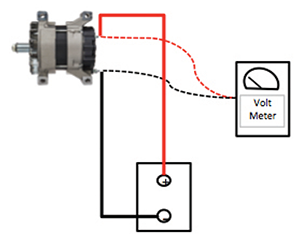
Alternator Cable Test with Automated Tester
Alternator Cable Test with Carbon Pile
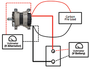
STEP 5 – TEST ALTERNATOR
- Check regulator by measuring alternator voltage at idle. Voltage should be 13.8 – 14.8 V (Figure 5A).
- Increase engine RPM and measure voltage again. The difference between measurements should be less than 0.5 V.
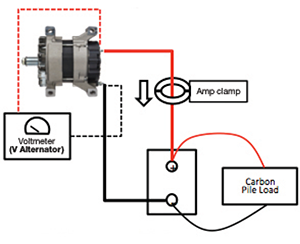
- Check output by increasing load until voltage reads 13.5 V while engine revved (Figure 5B).
- Output should be at least 90% of the alternator’s rating.
Alternator Test Diagrams
Follow prompts if using an autotester.
Alternator’s Regulator Test with Voltmeter
Alternator’s Output Test with Carbon Pile
Diagnostic Downloads & Videos
